Description
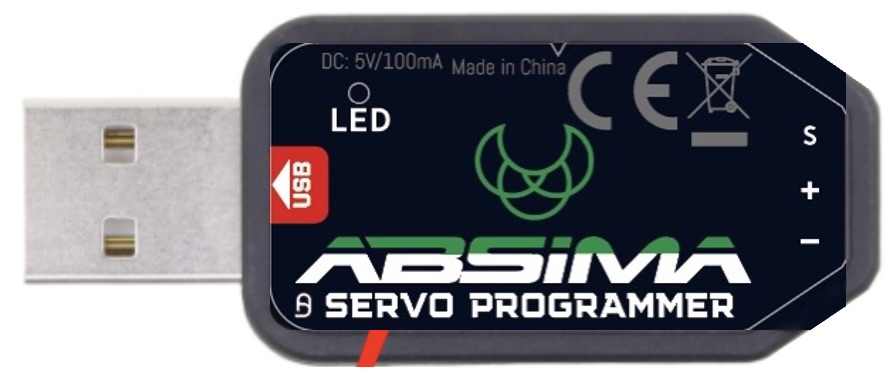
This USB adapter is only applicable for ABSIMA programmable servos marked with SMART SERVO.
suitable for the following programmable Absima servos:
- ST23DBF Team Spec.
- ST50DBT Team Spec.
- LP16DBF Team Spec.
- LP20DBT Team Spec.
- ST18DBF Race Spec.
- ST40DBT Race Spec.
- LP15DBF Race Spec.
- LP19DBT Race Spec.
- LP34DBT Crawler Spec.
System Requirements
1. operating voltage: USB(5V/500mA).
2. operating system: Windows XP/Windows Vista/Windows 7/Windows 8/Windows10 ( 32/64bit).
3. application: ABSIMA programmable servos with “SMART SERVO” marking.
1. operating voltage: USB(5V/500mA).
2. operating system: Windows XP/Windows Vista/Windows 7/Windows 8/Windows10 ( 32/64bit).
3. application: ABSIMA programmable servos with “SMART SERVO” marking.
THE NECCESSARY SOFTWARE CAN BE FOUND HERE : Software Competition Servos – OneDrive (sharepoint.com)

Parameter Einstellungen:
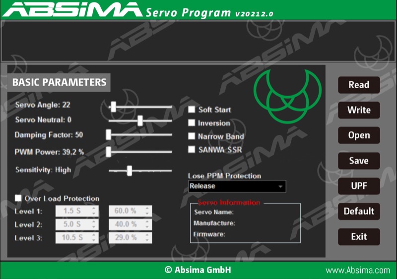
1. Servo-Angle: set the servo rotation angle.
2. Servo-Neutral: Adjust the servo neutral position Note: If the transmitter rotates to the neutral position and the servo does not
2. Servo-Neutral: Adjust the servo neutral position Note: If the transmitter rotates to the neutral position and the servo does not
stay in the appropriate position, you can change this value to adjust the servo horn. This is equivalent to trimming the
transmitter channel.
3. PWM Power: Set the servo output power. The higher the output power, the higher the servo torque and the speed, but also
3. PWM Power: Set the servo output power. The higher the output power, the higher the servo torque and the speed, but also
the power consumption is higher.
4. Damping factor: Set the damping of the servo.
5. Sensitivity: Set the deadband (sensitivity) of the servo.
6. Soft Start: Slow recovery when the servo is turned on. As soon as the servo is switched on, it will rotate smoothly to the
4. Damping factor: Set the damping of the servo.
5. Sensitivity: Set the deadband (sensitivity) of the servo.
6. Soft Start: Slow recovery when the servo is turned on. As soon as the servo is switched on, it will rotate smoothly to the
position of the current input signal. Note: This function is used to prevent damage caused by incorrect mounting of the servo
when switching on.
7. Inversion: Setting of normal and reverse rotation of the servo.
8. Narrow Band: FUTABA SR-Modus
9. SANWA SSR: SANWA SSR-Modus. Note: Enable this function to support the SANWA SSR high speed mode. The servo
7. Inversion: Setting of normal and reverse rotation of the servo.
8. Narrow Band: FUTABA SR-Modus
9. SANWA SSR: SANWA SSR-Modus. Note: Enable this function to support the SANWA SSR high speed mode. The servo
angle may not be accurate, it needs to be readjusted.
10. Lose PPM Protection: Signal loss protection, there are three functions to choose from:
10. Lose PPM Protection: Signal loss protection, there are three functions to choose from:
a. Release: Non-Protection
b. Maintain position: Remains in the position before the signal loss
c. Neutral position: Back to neutral position (1500uS position)
11. Overload protection: Set the servo blocking protection. There are three levels, which are activated by ticking:
Stage 1: Set the start time and power value of the primary protection.
Stage 2: Setting the start time and power value of the secondary protection.
Stage 3: Setting the start time and the power of the tertiary protection.
Note: The left side is used to set the protection start-up time, the right side is used to set the output power after the start-up
protection is activated.
12. Servo-Informationen: Servo-informationen. including servo model, version date and firmware-name.
Servo Name: Servo-Model
Manufacture: Date of servo version
Firmware: Servo firmware name
12. Servo-Informationen: Servo-informationen. including servo model, version date and firmware-name.
Servo Name: Servo-Model
Manufacture: Date of servo version
Firmware: Servo firmware name
THE NECCESSARY SOFTWARE CAN BE FOUND HERE: Software Competition Servos – OneDrive (sharepoint.com)

